node
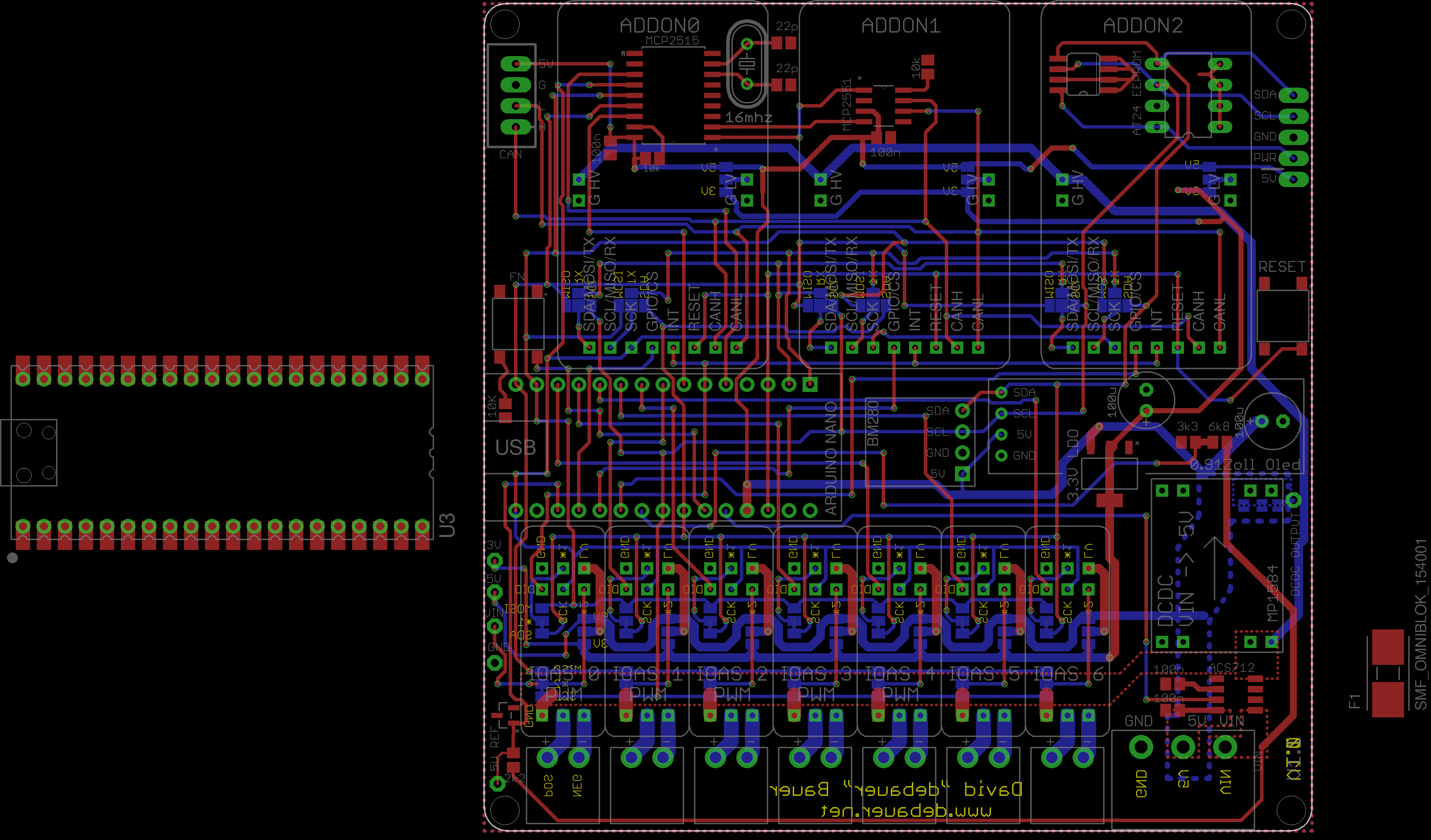
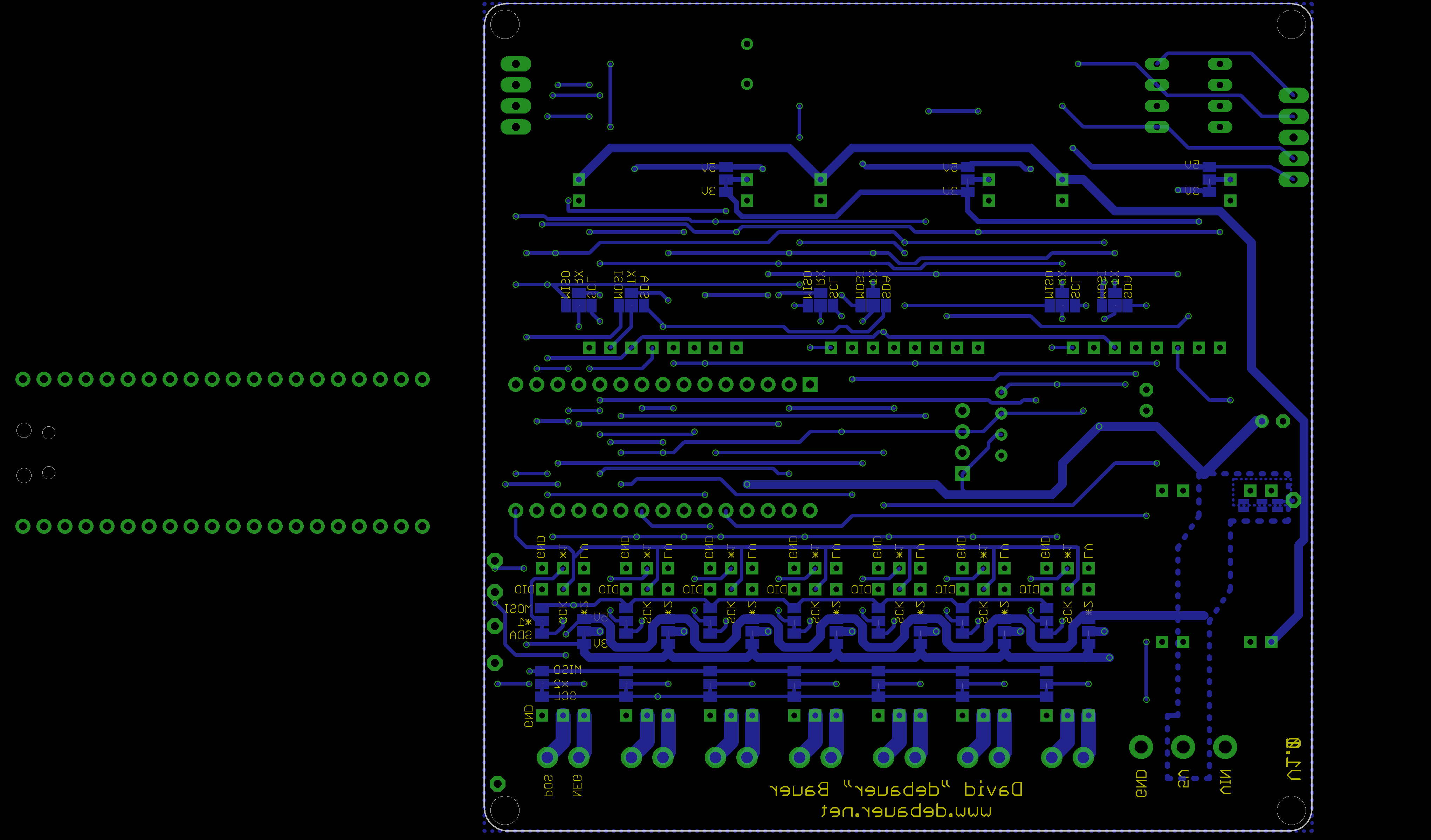
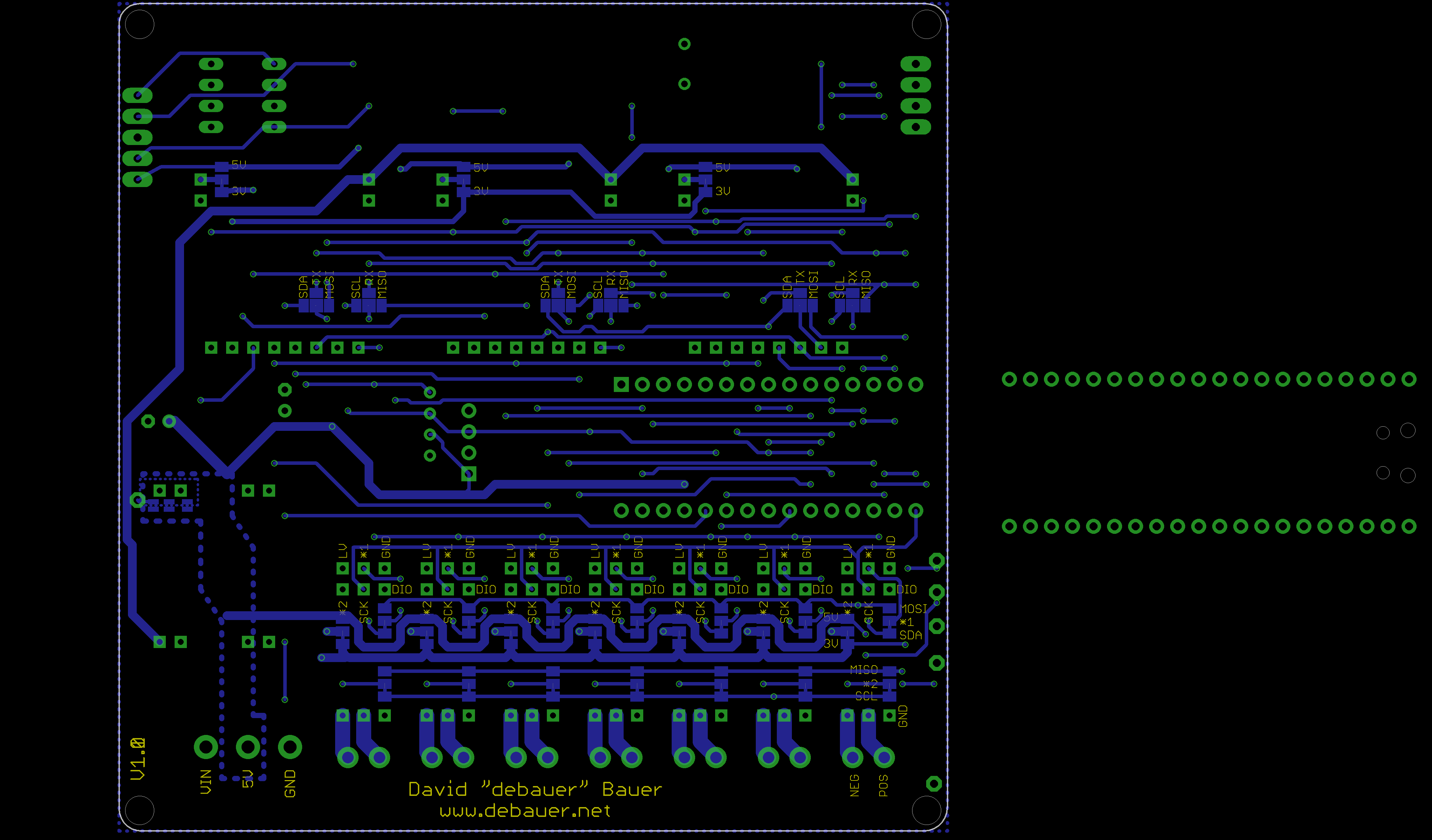
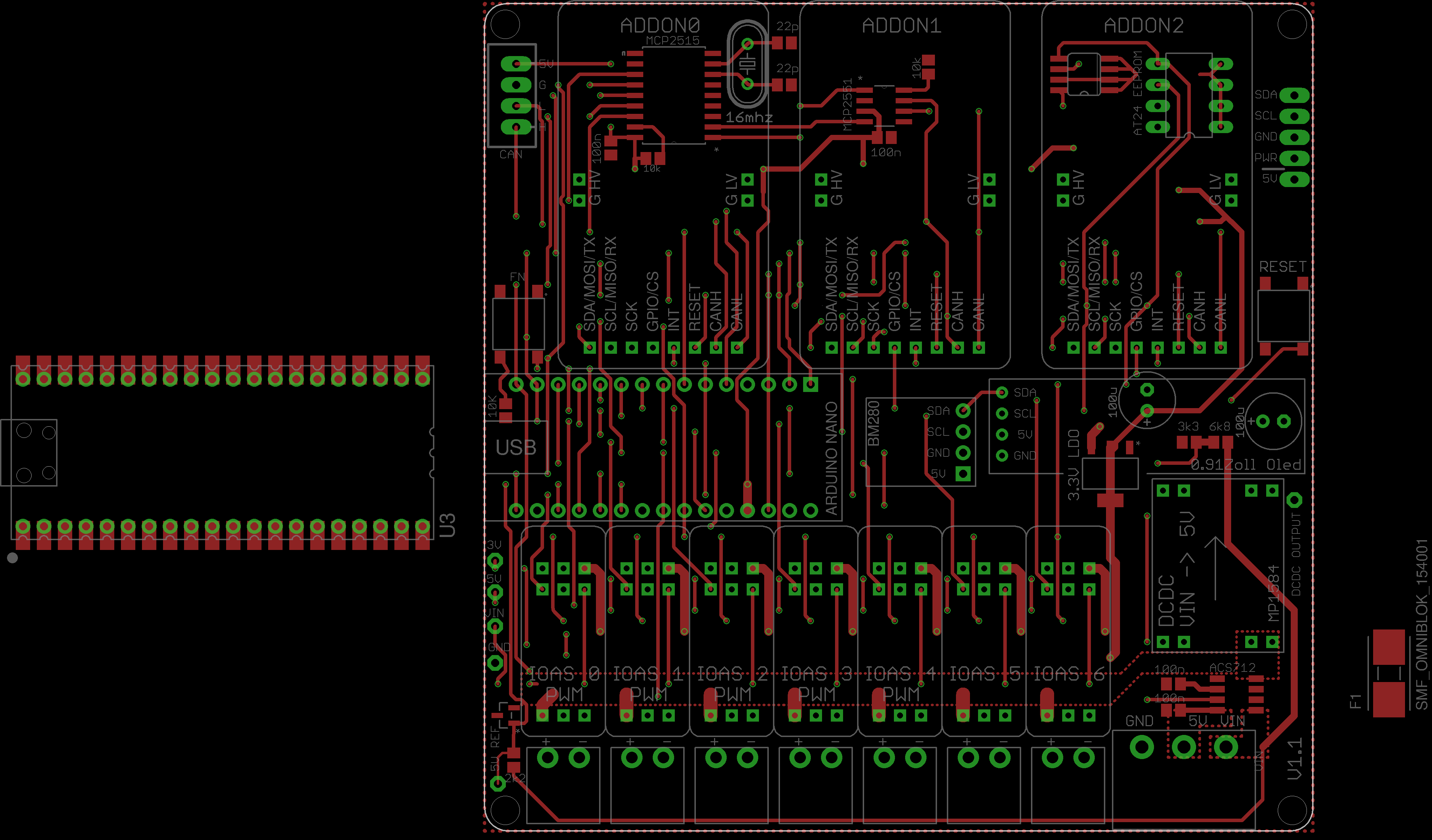
Central camper node board for control, sensing, and expansion modules. The board accepts an Arduino Nano as the controller, interfaces with the camper CAN bus, and provides several fused or configurable interfaces for outputs and add-ons.
Function
- MCU footprint for an Arduino Nano 3.0 with SPI, I2C, UART, analog inputs, and reset/button circuitry.
- CAN interface via MCP2515 and MCP2551 with a 16 MHz crystal.
- Seven IOAS output slots for switching output modules, each with its own 2-pin output connector.
- Three large add-on slots with CAN, SPI/I2C/UART signals, reset, interrupt/GPIO, and configurable logic supply voltage.
- I2C peripherals for a BME280 environmental sensor, 0.91-inch OLED, and AT24C EEPROM.
- Power supply from camper/LiFePO voltage, with a 5 V switching regulator, 3.3 V LDO, current measurement, and voltage measurement.
Controller and Bus
The Arduino Nano is the central control module. The key signals are assigned to named nets:
- SPI: MOSI, MISO, and SCK for the MCP2515 and add-ons.
- CAN: D4 as chip select and D2 as interrupt for the MCP2515.
- I2C: SDA/SCL for EEPROM, BME280, OLED, and add-ons.
- UART: RX/TX are available on the add-on interfaces.
- A7 measures the output of the ACS712 current sensor.
- A3 measures the LiFePO/vehicle supply voltage via a resistor divider.
- A6 is configured as a button input.
The CAN connector X1 brings out CANH, CANL, GND, and P5V. The MCP2515 operates on the SPI bus, while the MCP2551 provides the physical CAN interface.
Power Supply
J1 is the input for VIN/LiFePO, 5 V, and GND. The 12 V rail is distributed on the board as P12KFZ1 and measured via the ACS712. The MP1584 DC-DC module generates the 5 V rail, and an LM1117 generates 3.3 V from it. Test points are provided for GND, P5V, P3V3, and P12KFZ1.
The Arduino analog reference input is connected through an LM4040 reference. Jumpers JP25, JP27, and JP28 can connect the DC-DC output to P5V.
IOAS Outputs
The seven IOAS slots, IOAS0 through IOAS6, accept output modules and each route a 2-pin output to J2 through J8. All IOAS modules receive P12KFZ1, GND, and a selectable logic supply voltage.
- IOAS0: D3, PWM-capable.
- IOAS1: D5, PWM-capable.
- IOAS2: D6, PWM-capable.
- IOAS3: D9, PWM-capable.
- IOAS4: D10, PWM-capable.
- IOAS5: D7.
- IOAS6: D8.
For each IOAS slot, 3-pin jumpers select the logic supply between P3V3 and P5V. Additional jumpers route auxiliary signals to the shared buses, for example I2C or SPI signals.
Add-on Slots
ADDON0 through ADDON2 are large expansion slots. They provide P12KFZ1, GND, CANH/CANL, reset, SCK, a chip-select/GPIO signal, and an interrupt signal. The logic supply of each add-on is selected between P3V3 and P5V via JP22 through JP24.
The chip-select lines are assigned to the Arduino analog pins:
- ADDON0: CS_A0.
- ADDON1: CS_A1.
- ADDON2: CS_A2.
The signals SDA/MOSI/TX and SCL/MISO/RX are assigned to the appropriate bus functions via solder jumpers. This allows add-ons to be used as I2C, SPI, or UART expansions depending on the module.
Sensors and User Interface
The board is designed to accommodate a BME280 module for temperature, humidity, and air pressure, a 0.91-inch OLED, and an AT24C EEPROM on the I2C bus. S1 is the reset button, and S2 is a user button on the BUTTON net.
board images