rpi_hat
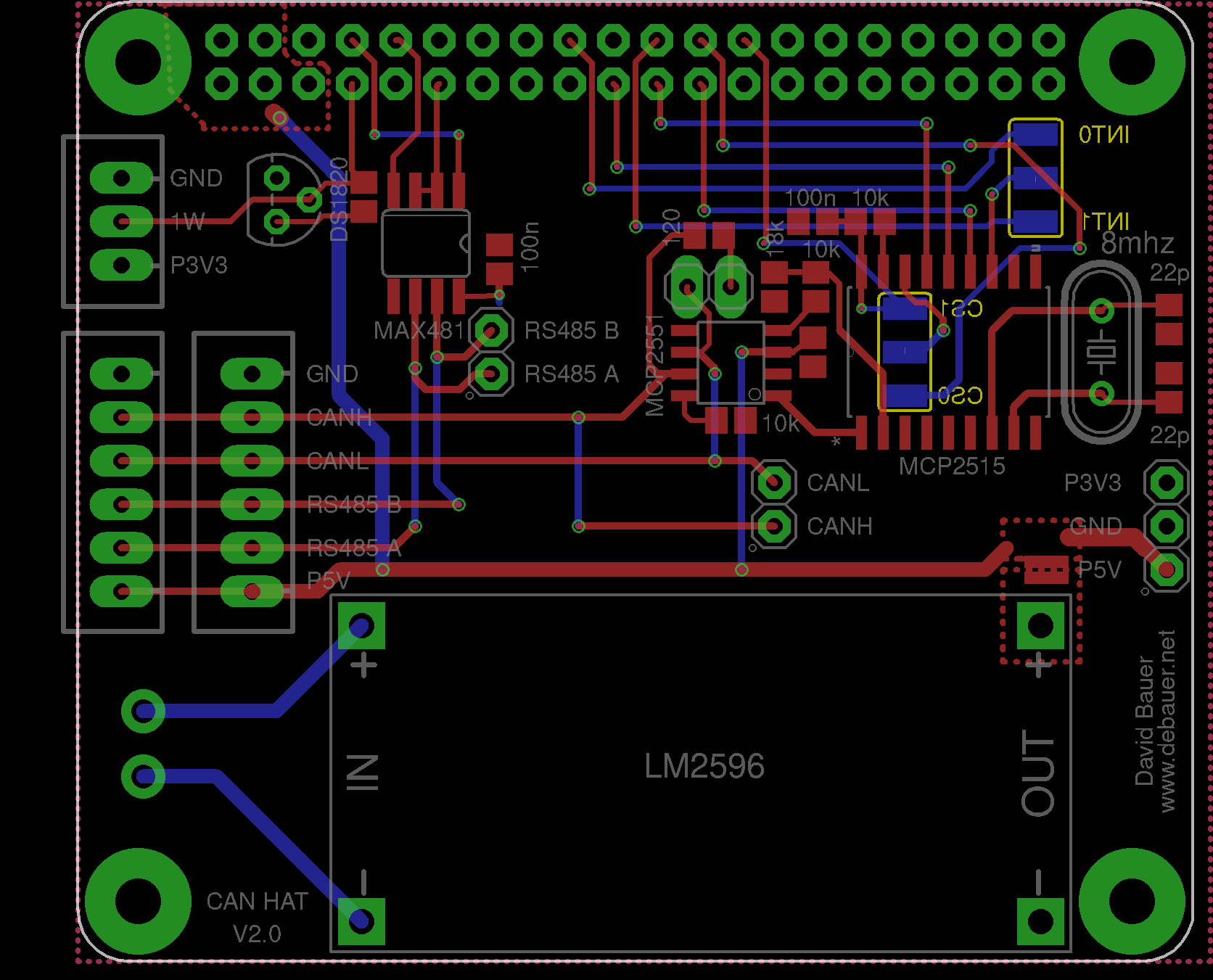
Raspberry Pi HAT for the camper van with CAN, RS485, and 1-Wire. The board plugs onto the 40-pin Raspberry Pi B+ GPIO header and provides the communication and power lines used in the camper via pluggable connectors.
Function
- CAN interface via MCP2515 on the Raspberry Pi SPI bus.
- CAN transceiver MCP2551 with a 120-ohm termination resistor that can be enabled via jumper.
- RS485 interface via MAX481 on the Raspberry Pi UART.
- 1-Wire connection on GPIO4 with a DS1820/DS18x20 temperature sensor and a 3.3 V pull-up resistor.
- Power supply via an LM2596 step-down module, distributing 5 V, 3.3 V, and GND to the board connectors.
Interfaces
The two 6-pin JST-XH connectors X1 and X2 are wired in parallel and form the camper bus. They carry:
- P5V
- RS485 A
- RS485 B
- CANL
- CANH
- GND
X3 is a 3-pin 1-Wire connector with P3V3, 1W, and GND. In addition, a DS1820 in a TO-92 package is intended to be mounted directly on the board.
JP1 brings out CANH/CANL on a 2-pin header. JP3 brings out RS485 A/B on a 2-pin header. JP4 provides P5V, GND, and P3V3 as a service or expansion connector.
Raspberry Pi Pin Assignment
- SPI: MOSI, MISO, and SCK connect the Raspberry Pi to the MCP2515.
- CAN chip select: selectable via JP8 as either CE0/GPIO8 or CE1/GPIO7.
- CAN interrupt: selectable via JP7 as either GPIO24 or GPIO25.
- RS485 direction: GPIO17 switches DE and /RE of the MAX481.
- 1-Wire: GPIO4.
- UART: the MAX481 is connected to the Raspberry Pi UART pins.
Power Supply and Jumpers
J1 is the input for the external power supply. The LM2596 module generates the 5 V rail from it. JP5 and JP6 connect the output of the step-down module to P5V. P5V powers the Raspberry Pi 5 V pins, the bus connectors, and the MCP2551; P3V3 comes from the Raspberry Pi and powers the 3.3 V logic such as the MCP2515, MAX481, and 1-Wire.
JP2 enables the 120-ohm CAN termination between CANH and CANL. The termination should only be enabled if this HAT is located at one end of the CAN bus.
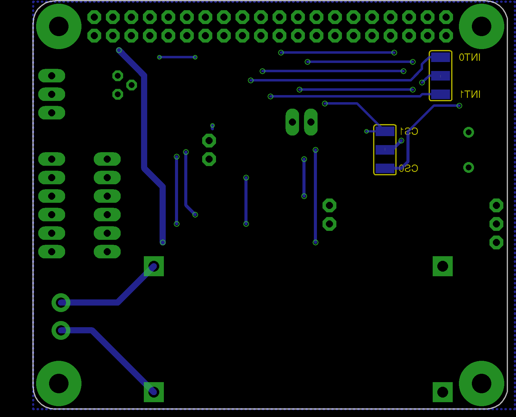
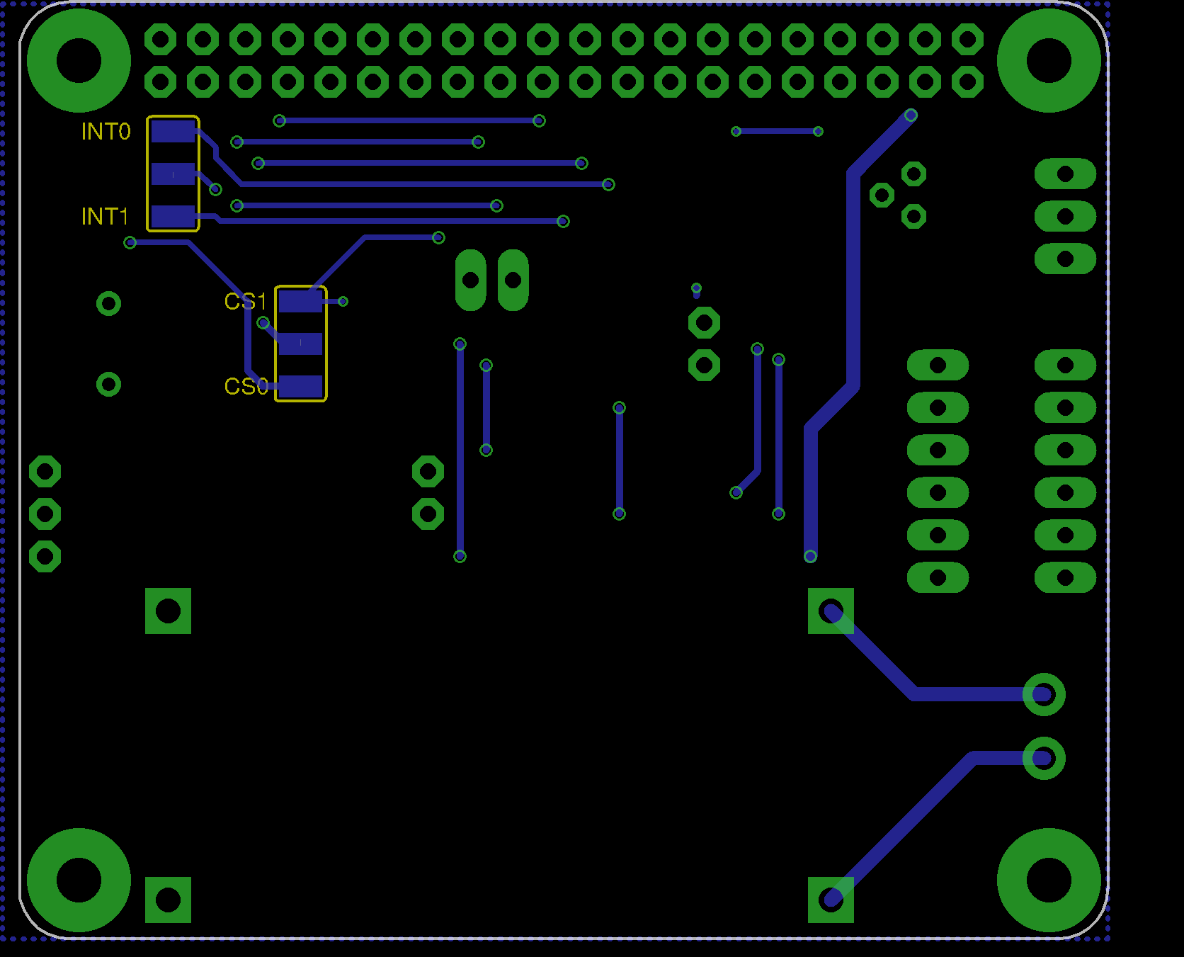
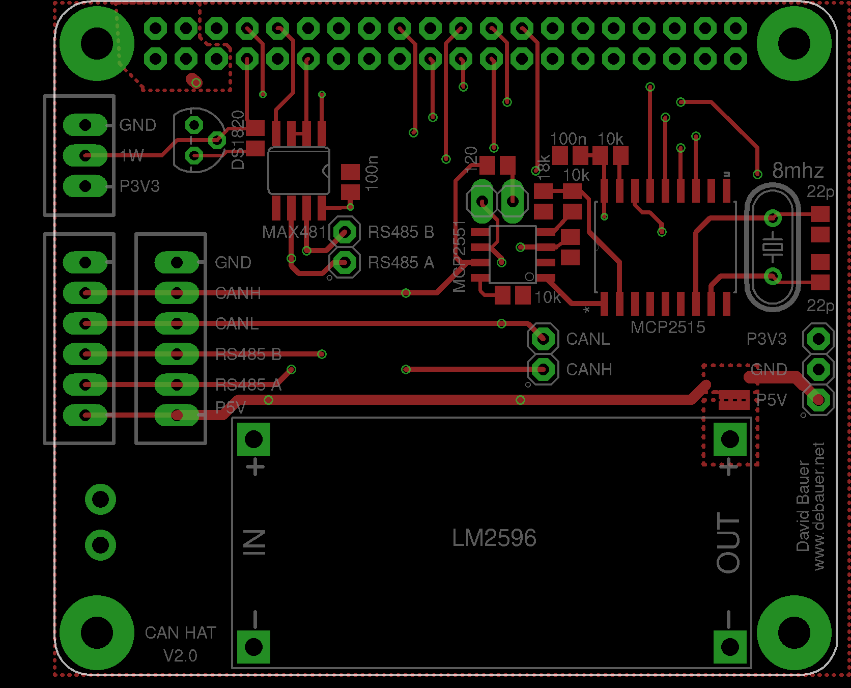
board images