can
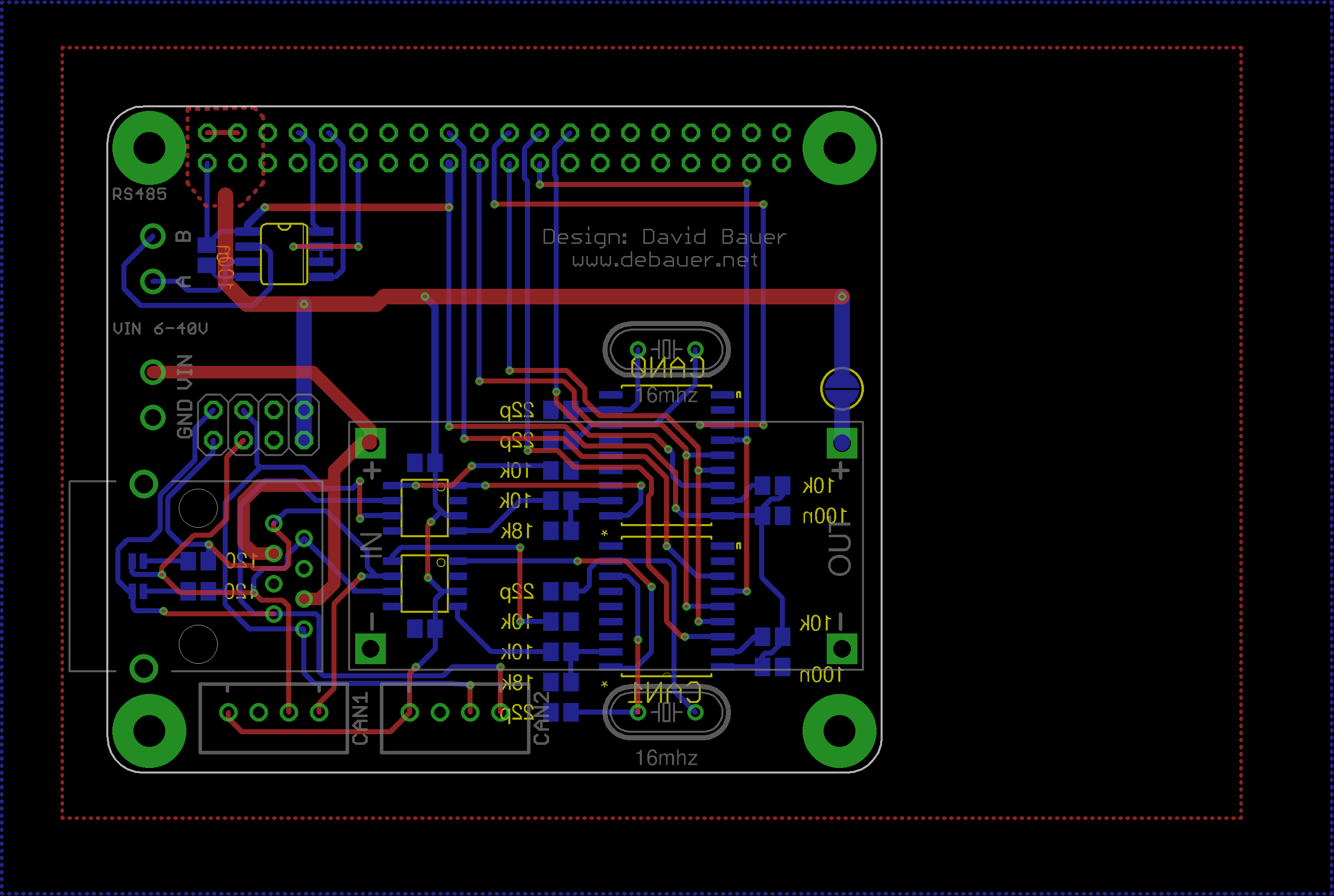
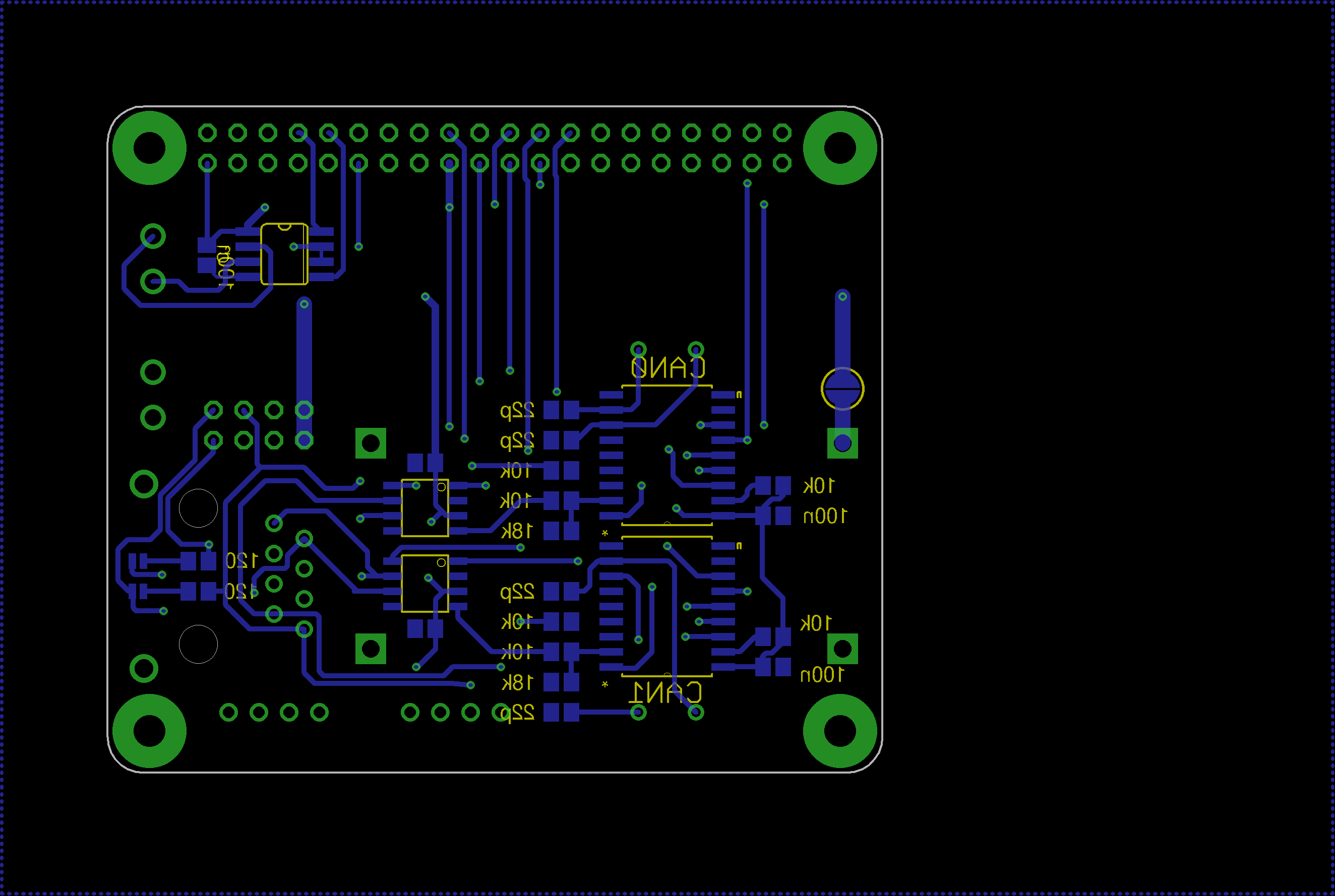
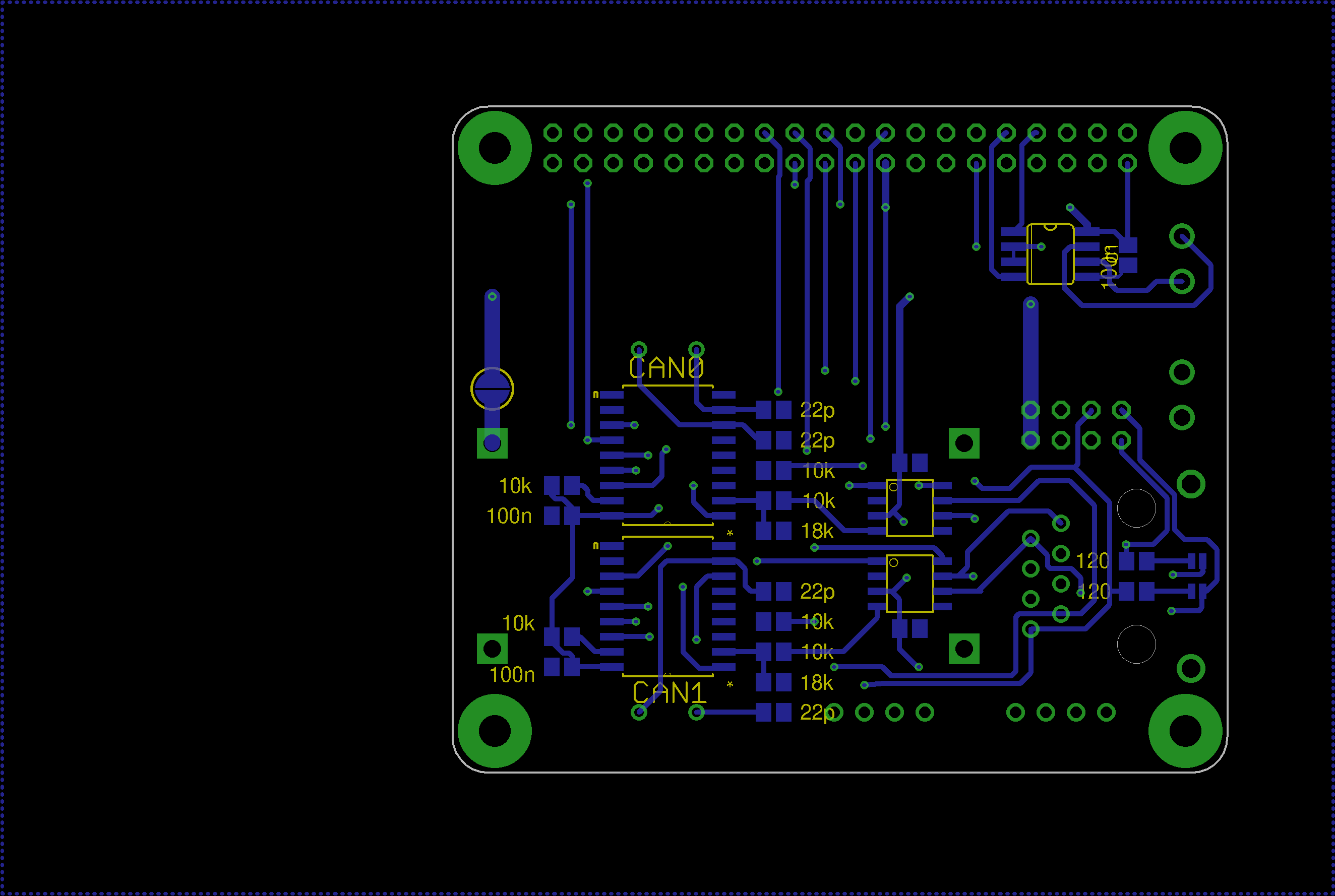
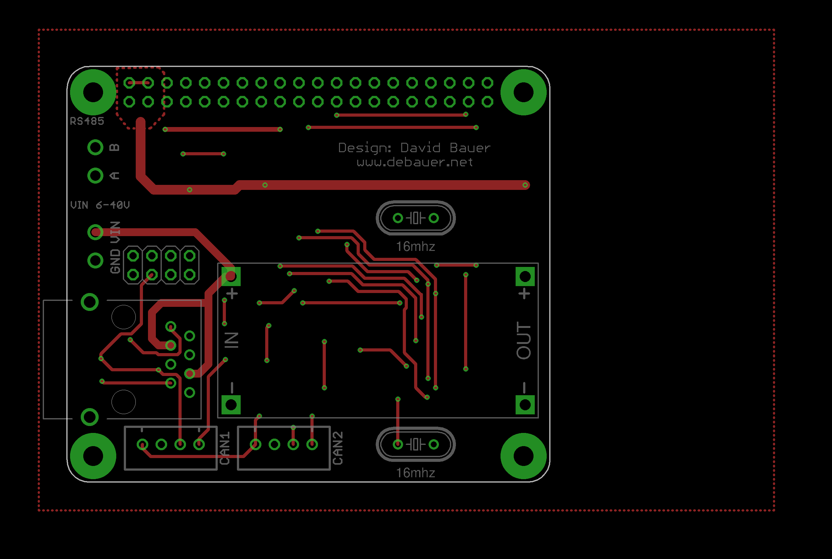
Raspberry Pi interface board with dual CAN, RS485 and wide-range power input. The board is built around the Raspberry Pi B+ 40-pin header and exposes industrial-style communication interfaces for embedded or automation projects.
Function
- Two independent CAN channels based on MCP2515 SPI CAN controllers and MCP2551 CAN transceivers.
- Each CAN controller uses a 16 MHz crystal.
- SPI connection to the Raspberry Pi with separate chip-select and interrupt lines for both CAN channels.
- RS485 interface based on a MAX481 transceiver.
- Wide-range VIN input marked for 6-40 V operation.
- LM2596 step-down module footprint for generating the local 5 V rail.
- RJ45 and JST connectors for external bus wiring.
Raspberry Pi Interface
The board plugs into the Raspberry Pi B+ compatible 40-pin header. The CAN controllers share the SPI bus using MOSI, MISO and SCK, with CS0 and CS1 as separate chip selects. INT0 and INT1 provide interrupt lines back to the Raspberry Pi. The RS485 section uses the Raspberry Pi UART signals.
CAN Interfaces
The two CAN channels are implemented as separate MCP2515/MCP2551 pairs. The schematic names the physical bus nets CANH1/CANL1 and CANH2/CANL2. Termination resistors and solder jumpers are included so the board can be configured depending on its position in the bus.
Power and Connectors
VIN and GND are brought in through a terminal connector, with the board marking the input range as 6-40 V. The LM2596 module generates 5 V for the Raspberry Pi and onboard logic. Additional connectors expose CAN and RS485 wiring, including labelled A/B pins for RS485.
board images